Sensing long cane · Prototype · 2026

NORDIC

Notices the kerb, the step and the branch before you reach them, and tells your hand.

Depth
8 × 8 zones · 15 Hz
Overhead
0.8 – 2.5 m
Cue
2 motors
Runtime
≈ 10 h

What it does

It adds what the tip can't reach: the drop a metre ahead, and the branch at head height.

How it sees a kerb

A few degrees of tilt make flat ground look a kerb deep, so NORDIC never thresholds distance. It predicts where the ground should be in each of 64 zones and watches for it to disagree.

A browser re-enactment of the detection logic in our simulator and firmware, with simplified geometry and noise.
  1. Know where it points

    Gyro and accelerometer give the pod's tilt and sweep.

  2. Predict the ground

    Each zone gets the range flat ground would return.

  3. Measure

    64 real ranges, 15 times a second.

  4. Compare

    Further is a drop; closer is a step or an object.

  5. Confirm and cue

    Two of three frames agree, then the motor plays.

4 : 1

At 1.5 m, one degree of tilt error looks like a 26 mm step. A kerb is 100 mm. That margin is why attitude must be good to 1°.

Where it struggles

Direct sun blinds the depth sensor, so the cane gives a warning cue instead of going quiet. In shade, warnings come under a metre ahead. Very deep drops and corridor walls are still open problems. Ultrasound works in any light.

Inside the cane

Five systems, each designed, simulated and laid out on our own two boards.

Two motors, four rhythms

Where you feel it says where the hazard is. The rhythm says what it is; the repeat rate, how close.

Ground hazards
Finger-side motor
Overhead
Thumb-side motor
Repeat rate
1 s at 1.5 m, faster closer in
Drivers
2 × DRI0056, one I²C bus each

Animated from our design values. Anything not yet measured on the bench is illustrative.

Specifications

Our design targets, and where each one stands today.

Design targets and current status
MeasureTargetWhere it stands
Drop-off warning≥ 1.0 m ahead of the leading footSimulated ≥ 1.05 m indoors; under 1.0 m in shade
Detection rate≥ 90 % of approachesSimulated 148 of 148 indoors
Smallest ground change100 mmBy design Threshold from 50 mm
Overhead range0.8 – 2.0 mSimulated 1.70 m bar warned 1.5 m ahead
False alarms≤ 2 per 100 mOpen None indoors; 1 – 5 in shade; walls too many
Depth frames15 HzBy design 15 Hz, 8 × 8 zones
Detection to cue≤ 300 msEstimated ≈ 200 – 250 ms
Battery life≥ 8 hEstimated ≈ 10 h
Standby power< 4 mWEstimated ≈ 0.6 – 0.9 mW
Charge to 90 %≤ 3 hAt risk ≈ 3.2 – 3.6 h at 750 mA
Calibration≤ 60 sTo test Guided, three steps
Fall detection≥ 90 % of staged fallsTo test Grip timing plus motion
Alarm loudness≥ 85 dB at 1 mBelow target ≈ 68 – 69 dB, datasheet

Look closer

Drawn from our own design files. Select a marker to zoom in.

A · Circuit boards

Four layers, designed in KiCad, made by JLCPCB. Rev H, 6 Oct.

Handle board 197 × 27.2 mm · 105 parts

The populated top of the handle board: power parts at the left, the long mounting area for the motor drivers, the processor socket, and the grip sensor and cable connector at the right.
  1. 5 A fuse · charger · buck-boost to 3.3 V

    The cell meets a fuse first, then the regulator over a short, wide trace.

  2. 2 × DRI0056 · own I²C bus each

    The two haptic driver boards hang under the board on these mounts.

  3. ESP32-P4 · power latch · cell protection

    The module plugs in on top; the latch and battery protection sit beneath it. Off means fully off.

  4. Schmitt oscillator · guard follower

    No ground pour under the sense node on any layer, and its own clearance rule.

  5. 20-way FFC · 0.5 m · buffered

    Every signal passes a buffer that lets go when the processor is off.

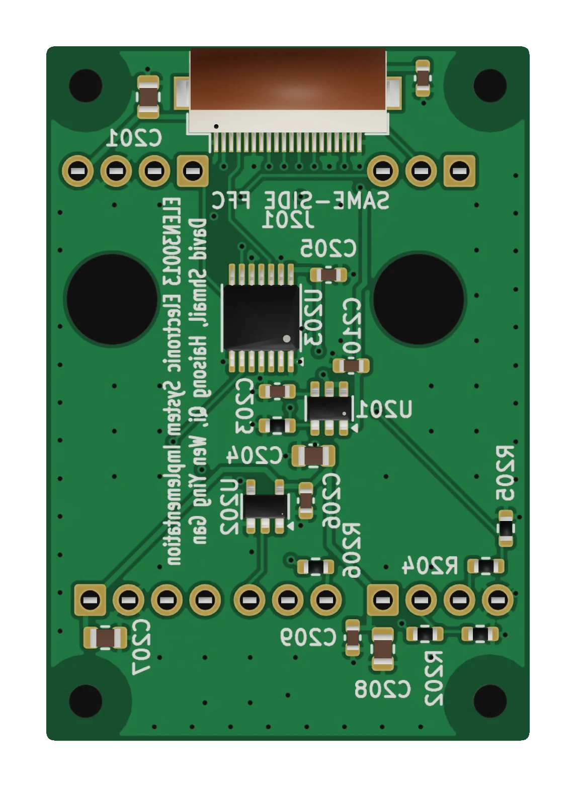
Pod board 32 × 46 mm · parts side

The populated underside of the pod board: the flat cable connector along one edge, the sensor power switch and logic buffers in the middle, and the sensor terminals along the other edge.
  1. Right-angle · 2 mm tall · 20 ways

    Lets the cable run straight back along the shaft.

  2. Load switch · 1.9 ms soft start

    Depth sensor and sonar are cut off when idle; the motion sensor stays on to wake the cane.

  3. One SPI bus · two sensors

    Keep the processor's signals out of an unpowered sensor.

  4. Depth · sonar · 10 µF + 100 nF each

    Every sensor wire has a series resistor and local decoupling.

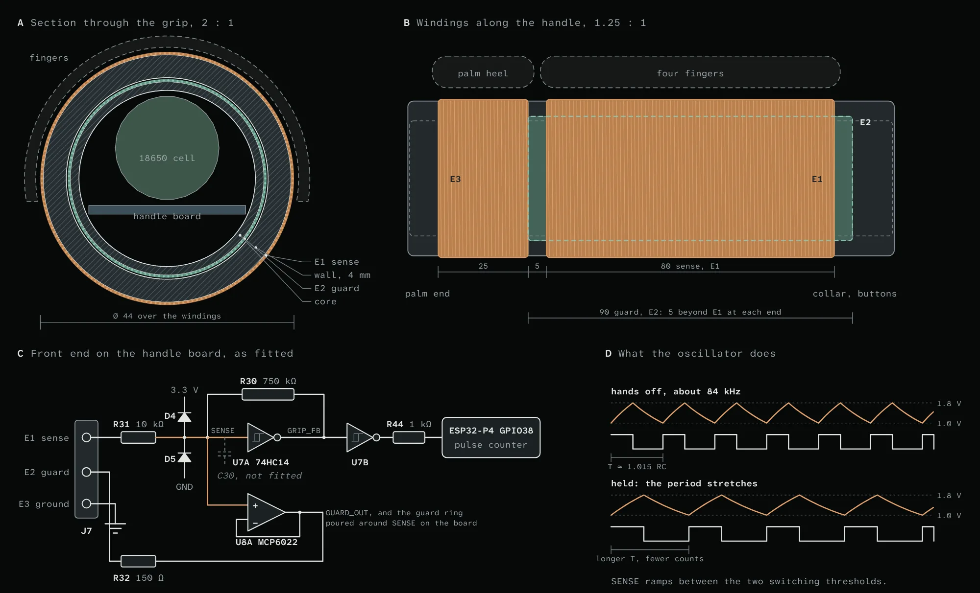
B · Grip sensor

A hand adds a few picofarads and the oscillator slows.

Capacitive grip section · windings · circuit · waveform

Drawing of the grip sensor: a section through the grip with the sense winding outside the printed wall and the guard winding on the core, the windings along the handle, the oscillator and guard circuit, and the waveform at the sense node.
  1. ≈ 80 – 85 kHz hands off, expected

    There is no timing capacitor: the sense winding is it, so a hand slows the oscillator directly.

  2. MCP6022 follower · ≤ 150 pF coupling

    The guard winding follows the sense voltage, so the electronics inside the grip are invisible.

  3. ≈ 2 × signal on battery, predicted

    Gives a floating, battery-powered cane a return path through the palm.

  4. 74HC14 + 750 kΩ · 10 ms gate

    The processor counts edges for 10 ms. Held is more than 6 % down.

Values as fitted on 8 Oct. Hand figures are design estimates and simulation.

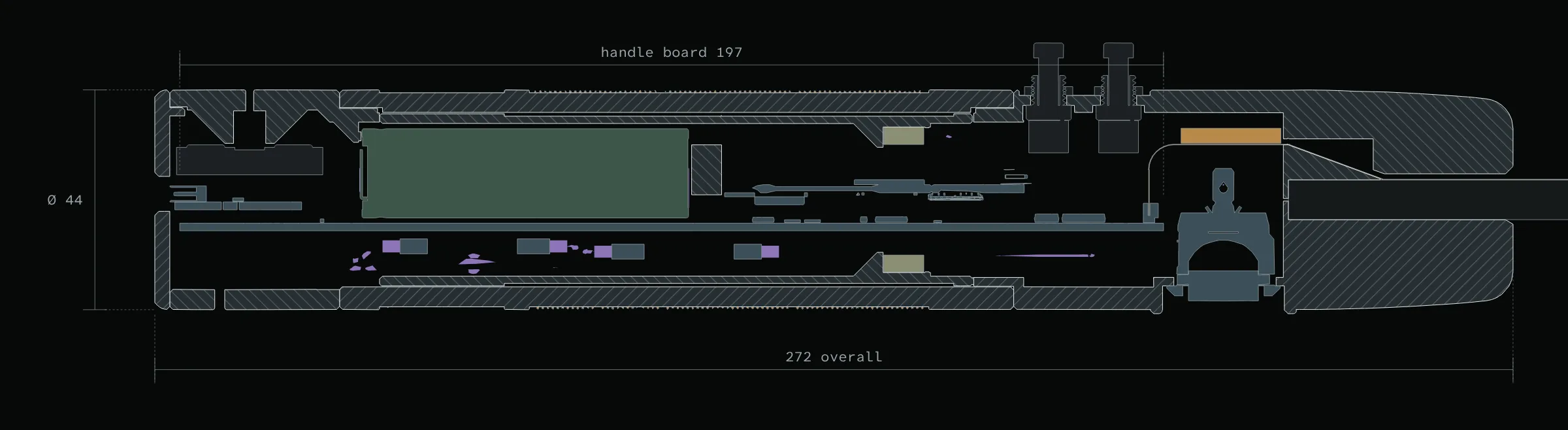
C · Mechanical

Cut from the 15 Oct CAD. Hatched faces are printed PETG.

Handle 272 mm · Ø 44 mm grip

Section through the handle: end cap and charger at the left, the cell and the long board inside the grip core, the motors in the core wall, and the collar with buttons, rocker and shaft at the right.
  1. Clamshell · Ø 8 mm carbon shaft

    Two printed halves close on the shaft and carry the buttons and the guarded rocker.

  2. Windings on the shell · guard on the core

    The sense and ground windings are wound straight onto the printed shell.

  3. 2 × LRA · 10 × 10 × 3.5 mm

    One on the thumb side, one under the fingers, so each cue lands where it means something.

  4. 18650 · 197 mm board, end to end

    The weight sits in your hand, not out along the shaft.

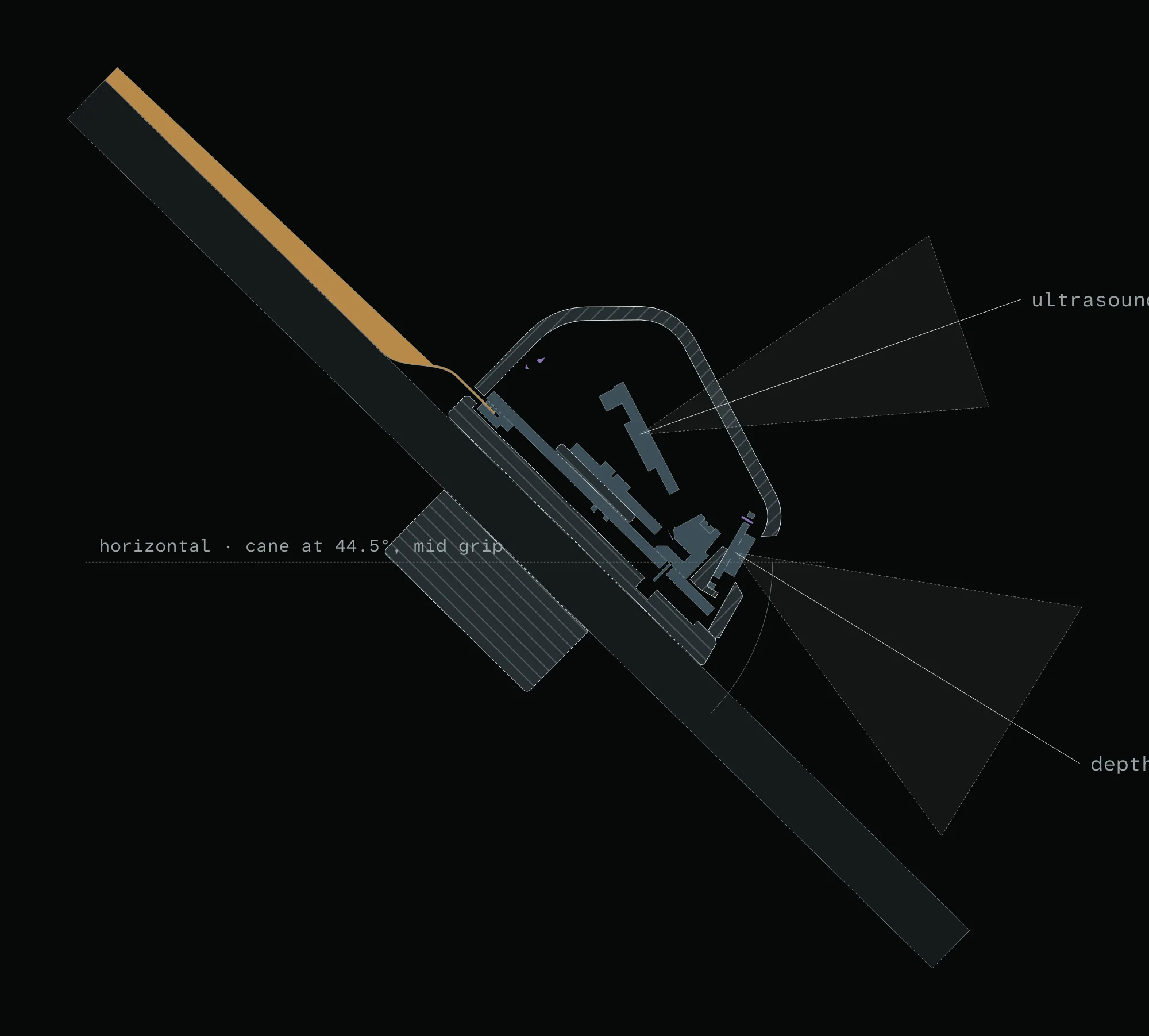
Sensor pod 54 mm · clamped to the shaft

Section through the sensor pod at the angle the cane is held, with the depth sensor's field of view toward the ground ahead and the ultrasonic beam toward head height.
  1. 4 × M5 · no glue

    Base and clamp cap close on the shaft, so the pod can be set for each cane.

  2. Motion sensor + depth sensor, no joint

    Nothing flexes between them, so the tilt measured is the tilt the depth sensor has.

  3. 45° field · 26° – 42° below horizontal

    Set to the shaft, not the horizon, so the ground stays in view for any pitch from 27° to 57°.

  4. 25° – 9° above horizontal

    Looks just above horizontal, at chest and head height.

“In use” is drawn at 44.5°, a mid grip. Beam widths are cut short.